1
Introduction
Once the first VPNs were established as layer 3 services with IPSec, it
was apparent that better layer 2 services were needed to separate the different
users’ virtual networks. This is because customers want to connect their LANs
at different sites without trouble and complexity. They often need speed
greater than IPSec can deliver for a given cost. Additionally, they want
transparent networks; preferable looking as if it is a single LAN. There is
also a need for a solution where the layer 3 protocol is not IP, or when it is
IP but with own address ranges and routing protocols such as OSPF.
The solution is to deliver one or more VLANs to the customer, and in
some scalable and manageable way transport them via a core backbone built up on
Gigabit Ethernet or similar technology. There are several issues to have in
mind when designing these networks, besides the cost of deployment; I will
examine these issues in this report.
This thesis explains the standards currently in use, the problems that
can arise, their solutions, and also a proposal for a technique to use in a
modern network backbone. Today VLANs are generally limited to distribution
within cities. In the near future national VLANs are going to be used. This
will require some testing, because it is not common to do so today and it is
not clear that the technique will operate over long distances. It is also not a
scalable solution, due to the maximum number of VLANs that are available for
use in most existing network equipment. The theoretical limit[1] of the
number of VLANs is 4094, and the tables in some hardware can only hold up to
3000 records [4]. That is not enough for use by a Carrier for Carriers
(i.e., a backbone operator).
A comparison of VLAN tunneling in VMANs and MPLS was made, and an
evaluation of which is the best solution will be presented below. This solution
must solve the scalability problem, but unfortunately it also increases
management complexity. This solution was evaluated both in separate test beds
with the same type of network hardware used in a backbone and also in a real backbone.
According to common sense, de facto standards, and [9], a traditional layer 3 VPN (based on IPSec) needs to
be:
·
Manageable
·
Secure
(offering: authentication, encryption, no change of data in transit)
·
Reliable
·
Possible
to implement in the backbone without too many changes, and with existing
hardware
·
Cost
effective
For a layer 2 VPN, it seems like the same needs exists, except that the
security issues are different. When providing only layer 2 only connectivity,
encryption of the payload is trickier, although the connection should be seen
as if it were a traditional leased line.
When a customer buys a layer 2 only service, he or she can run whatever
protocol(s) and use any addresses above this layer 2 service. To be able to
sell such a service, an ISP needs to build a slightly different network from
the usual IP network. To be able to run a layer 2 only network that coexists
with a layer 3 network, a complement to or replacement for the Spanning Tree
Algorithm is needed because of layer 2 loops that may be created. Extreme
Networks has come up with one solution: Ethernet Automatic Protection Switching
(EAPS). A short investigation of this can be found in this thesis in section 2.6.
1.1
Project
Goal
The goals
for this project were:
- See what is possible with the Extreme
Networks’ implementation of tunneling VLAN in VLAN. To understand how to
re-build a backbone to expand the number of VLANs that can be assigned to
customers.
- Build a test environment and evaluate
possible configurations. Evaluate with respect to speed and the
configuration needed
- Due to the complexity of large numbers of
VLAN ID assignments need for use nationally, some software may be needed
to keep track of everything. A Requirement Specification document
concerning such software is to be made, and if time allows, the basic
functions for such a system are to be implemented.
- Build a test environment and evaluate the
Extreme Networks MPLS hardware and software. Evaluate speed and the
configuration needed.
- Analyze
problems in providing a Layer 2 service. This includes large broadcast
domains, redundancy for both layer 2 and layer 3 and as noted above the
configuration complexities.
By examining the two major ways of tunneling layer 2 traffic in a backbone,
and how to implement them in an existing backbone without too much cost, it is
hoped that important customer needs will be satisfied. The success in
satisfying such needs is important for economic, social, and political reasons.
2
Layer 2
VPN
This chapter introduces the requirements for a Layer 2 VPN, and the
standards used, especially with respect to Extreme Networks’ implementation.
Here we will focus strictly on the standards and not say much about the
drawbacks and solution possibilities. However, these issues will be addressed
in chapter 4. First I will give an introduction to Virtual Private
Networks.
2.1
Introduction
to VPN
There is no exact definition of a VPN, but rather a lot of de facto
definitions. However, of these the one given in [11] is quite good:
“In a very general way, Virtual Private Networks (VPNs) are defined as
customer connectivity deployed on a shared infrastructure with the same
policies as a private network. This shared infrastructure can leverage a
service provider’s IP, Frame Relay, or ATM backbone and may or may not utilize
the public Internet.”
In my opinion, Gigabit Ethernet should be added to the list of backbone
technologies, and maybe something more specific should be said about what kind
of policies a private network offers. Perhaps it is a matter of different
interpretations, or perhaps what the market expects today, but I think most
people think of a VPN as an IP tunnel that is probably built upon IPSec and it
offers authentication, data integrity and encryption (see chapter 3). When talking about a layer 2 VPN, these
expectations have to be re-evaluated. Note that a layer 2 VPN as described in
this thesis only provides the rough equivalent of a leased line and does not
provide any guarantee for authentication, privacy, or non-repudiation.
A natural way of achieving the necessary connectivity is to connect all
offices within a company to the Internet. There are very few companies today
who do not want to be connected to the Internet; the exceptions being some high
security companies. After a connection is established to the Internet, the
different company branches want to communicate with each other. That can be
done in layer 3 (via IPSec) or at a higher layer (such as with SSL) over the
Internet. In addition, because of the “networked” economy, the company must
also securely connect to customers, suppliers, and even employees working from
home.
To make life simpler and to be able to increase effective bandwidth, the
development of VPNs needs to go further. A layer 2 solution avoids expensive
leased lines. Such a solution can provide a VLAN to a customer tunneling
through a backbone. The Gigabit Ethernet backbone is the most interesting case,
because of the bandwidth available and its simplicity. Thus in the end, the
customer only sees an Ethernet, and therefore can administer his own IP
addresses and route his traffic to an exit point (ISP) of his or her choice;
while still connecting geographically disperse sites.
2.2
Requirements
of a Layer 2 VPN
When a layer 2 VPN solution is provided, it has to meet several
requirements. Both for customers changing from a traditional leased line and
for new customers, high availability must be provided. This requires providing redundancy
between endpoints, thus no link can be a single point of failure.
Another requirement for this simple layer 2 VPN is that it is to be
delivered with a standard Ethernet port. This makes customer
connections simple. With a Gigabit Ethernet backbone little translation has to
be done. The customer traffic can traverse a dedicated VLAN or be transported
through a MPLS cloud in a VLAN tunnel.
Because of the above requirements redundancy
solutions have to be chosen accordingly, and amongst these the only proven
standard is the Spanning Tree Protocol. Today there exists new ring topology
driven standards like Ethernet Automatic Protection Switching (EAPS), and there
is further work in progress concerning the Spanning Tree Protocol, specifically
for extensions for Rapid reconfiguration (IEEE 802.1w) [21] and Multiple Spanning Trees (IEEE 802.1s). If
possible, a service where the customer can send 802.1Q tagged traffic in a dedicated tunnel should be provided.
A large part of a Layer 2 VPN is Service management. It has to be
fairly easy to enable such a VPN service, from the beginning (with small
numbers of VPNs) and up to the maximum limits of number of VPNs that it is
possible to provide. In all cases automatic configuration is desirable,
or at least as automatic as possible. A way of monitoring the service as well
as making changes to the service is also desirable. Also on the wish list is
that a way of dynamically decreasing or increasing the bandwidth should be provided.
When comparing layer 2 VPNs with the traditional Layer 3 VPNs, like
IPSec, the security issues are a bit different. For layer 2 VPNs it is
mostly up to the network provider to guarantee privacy. However, if the
customer is using the VPN to transport his own IP traffic, then it’s possible
to gain extra security by putting up firewalls at the customer ends of the
tunnel, which provide a layer 3 VPN on top of the layer 2 VPN. This will still
enable the customer to run his own IP addresses and routing protocols.
The final requirement for a Layer 2 VPN is that it must scale. It is
desirable to have as few limits upon the number of VPNs as possible, and
it should be possible to configure lots of VPNs without problems except for the
normal issues of their associated traffic load. Thus the limits should only be
related to the aggregation of traffic, not because they are each VPNs.
2.3
Layer 2
Tunneling Protocols
There are several ways of tunneling Layer 2 traffic, and they can be
divided into solutions provided at the service provider end and solutions at
the customer site. Examples of protocols that customers can use on their own
includes Cisco’s Layer 2 Forwarding protocol (L2F) [15], Microsoft’s Point-to-Point Tunneling Protocol (PPTP)
[16], and the merger of those two, Layer 2 Tunneling
Protocol (L2TP) [17]. Each of them provides a way of transporting PPP
traffic over IP, more or less, and was provided as a solution for dial-up
connections. L2TP is built into Microsoft’s Windows 2000 Workstation/Server,
and you can build Layer 2 tunnels between a Workstation and a Server, sharing
files, and playing games requiring protocols other than IP.
There is some work in progress to develop L2TP version 3 (where L2F is
called version 1 and L2TP is called version 2), called L2TPv3 [18]. This new version of L2TP tries to separate PPP from
L2TP, and therefore make it possible to tunnel other layer 2 protocols.
According to people in the IETF workgroup that are working with this, L2TPv3
will not be widely used as a
provider provisioned VPN solution to transparently tunnel Ethernet traffic
between two sites.
More interesting ways of tunneling Ethernet traffic are found in the
provider provisioned VPN solutions such as MPLS and secure VLAN tunneling.
These are lower level protocols, often built into ASICs, and not simply another
software implementation in a common operating system. I believe they are more
interesting because of the extra control the service provider gets, as well as
the scalability and simplicity issues. These techniques can also solve problems
other than providing a layer 2 VPN to a customer, see the following sections.
2.4
VMAN
2.4.1
Introduction
Extreme Networks’ implementation of VLANs in VLANs is called VMAN, and
is basically built upon another VLAN tag in the Ethernet frame header [3]. The configuration is very simple, just change the
Ethertype for VLAN in a switch and use the same VLAN commands as for normal
VLANs. Jumbo frames must also be enabled on the switch, because the frames have
to be larger than what the standards allow. The VMAN tag of 4 bytes is inserted
before the VLAN tag, thus the frame is four bytes larger.

Figure 1 - Ethernet frame with VLAN
The figure above contains an ordinary VLAN tagged frame. When running VMAN on a switch, the same type of header is inserted before the 802.1Q VLAN header, but with an Ethertype of 9100 so that the switches can recognize the frame as a VMAN frame. See Figure 2.
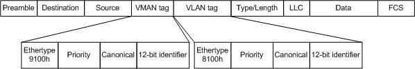
Figure 2 - Ethernet frame with both VLAN and VMAN
The main issue of VMANs, especially the implementations where it is not
possible to combine VLANs and VMANs in the same switch, is the design of the
network. A lot of planning and thinking has to be done to support and manage
this additional VLAN layer, and that will be described in section 4.2.
2.4.2
Advantages
VMAN initially seems quite simple to implement. The standard itself is
quite simple and thus easy to understand and deploy. Usually all hardware that
supports VMAN supports it from the beginning, thus theoretically no additional
hardware or software is needed. It is only necessary to configure the equipment
in order to deploy it.
2.4.3
Disadvantages
VMAN can be expensive because additional switches are currently required
outside the VMAN core. Further more we are limited to switches that support
VMAN. As there is no standard yet for VMANs an ISP can only use hardware from
one manufacturer due to compatibility problems. There may be some hardware
suppliers with the same solutions for an implementation, but most likely there
will be compatibility problems anyway.
Today, when using Extreme Networks’ products, some limits exist in the
core because a switch cannot run both VMAN and VLAN at the same time. This is
because the Ethertype for VLAN is changed from 8100 to 9100. Simple untagged
VLAN seems to be possible to tunnel in one VMAN, and therefore can be used
directly, but the port cost can be quite high if additional ports are needed to
distribute all VLANs to their correct destination. Each port in the core is
more valuable, and the idea with VLAN of sharing physical links and ports for
several LANs cannot be used.
The scalability seems okay in the beginning, but does not scale beyond a
practical limit of around 2500 VLANs assigned for customers in one region. It
is hard to keep track of all the VLANs and VMANs, and therefore an intelligent
tracking system is needed. One VLAN may stay within region A, another be
transported between region A and B, while a third one may be transported
between region B and C. Since no VLAN ID collision can be allowed, this
requires good planning and a tracking system.
The major drawback is that in order to be able to implement this, a set
of VMANs needs to be distributed “everywhere” in the core, this generates a lot
of unnecessary traffic. This is because that a core switch cannot look inside a
VMAN, and within each VMAN there may be VLANs that needs to be terminated in
each core node in the network. All traffic doesn’t need to be transported
everywhere, most only needs to go to the desired destination. Combined with the
need to place an extra physical switch right outside a VMAN node in order for
each VMAN to distribute the VLANs in it, the amount of hardware currently
required quickly exceeds what is reasonable.
2.4.4
How it
works
The VMAN concept is quite simple; it is just another way to tunnel a lot
of VLANs between one or more sites. An investigation of how if possible to
actually implement this, can be found in section 4.2.
2.5
MPLS
2.5.1
Overview
MPLS can be seen as a shim layer between layer 2 and layer 3 in the OSI
model [12]. It is similar to ATM virtual circuits and Frame
Relay, because only a label is used in the routing through a core network. Some
people call it layer 2.5. Despite the comparison with older and more expensive
solutions, MPLS seems to be a good compromise between multiple existing
standards. It provides a lot of good features while retaining flexibility and
ease of use.
The idea is to use Label Switching in the core network, with MPLS
enabled switches. Utilizing Transparent LAN Services (TLS), it is possible to
transport or tunnel, layer 2 traffic via a Label Switched Path (LSP) through a
backbone network. Each MPLS hop can be seen as a layer 3 hop, and all switches
on the way are identified by their IP address, announced via the Open Shortest
Path First (OSPF) routing protocol. It is also possible to tunnel normal layer
3 traffic in a MPLS LSP. Note that this is the usual task for MPLS, but with
TLS this becomes interesting for implementing layer 2 tunnels. Details of how
it works can be found in subsection 2.5.4 and onwards.
2.5.2
Advantages
MPLS is a well-known standard today. It is mature and it provides
everything that is necessary for a fast switching backbone to provide VPN
capabilities.
If two adjacent routers are both BGP peers and MPLS label switching
routers, all the label switching information is easily transferred via BGP-4. The
internal version of BGP, iBGP, is used for MPLS [7].
Extreme Networks are using dedicated MPLS add-on cards to provide secure
transit to a MPLS enabled core. Other layer 2 and layer 3 functionalities are
intact and unaffected by the addition of MPLS.
2.5.3
Disadvantages
A transition to MPLS can be expensive. The access switches/routers need
extra hardware and a special version of the software or MPLS capable devices
must replace them. Unfortunately this software often lags behind the normal
software releases, and therefore a MPLS-enabled node cannot frequently make use
of all the latest features that other nodes may use.
Today the hardware from Extreme Networks consists of expensive add-on
cards specially made for MPLS, without the fast implementation in ASICs that’s
possible once the standards are complete. Since MPLS as a working standard is
still evolving, the software for it is being upgraded all the time.
Another disadvantage of MPLS is the long time required to rebuild all
the LSPs when a link goes down. In a complex network a lot of CPU power is
required to calculate new LSPs. These tables also take considerable memory,
especially when recalculating all paths. It seems that this will not have much
impact in a modern core switch like the Extreme Networks’ Black Diamond,
because of the huge amounts of memory and processing power available both in
the switch and in the MPLS add-on card.
2.5.4
How it
works
Multi Protocol Label Switching tries to make use of a fast switching
technique based on a short 32 bit header, placed between Data Link and Network
headers. (Figure 3)
![]()
Figure 3 - MPLS shim header
A Label Switched Path (LSP), see Figure
4, is built up between two Label Edge Routers (LER).
Zero or more Label Switch Routers (LSR) can switch the traffic on the way in
between these two LERs. The first LER adds a label depending on which VLAN the
packet belongs to and another label based on an IP longest prefix match scheme,
i.e. a normal routing decision, to the next MPLS-hop. It then sends the packet
to next LSR or LER, depending on its own MPLS forwarding table. The LSRs in
between only look at the outermost 32 bit long label in the label stack and
forwards the packet to the next hop, according to it’s own forwarding table,
after the label is changed to its label for the next hop. The last LER strips
off the label and forwards the packet to the right interface/VLAN according to
the setup made for this specific LSP.
A typical MPLS network is shown in Figure
4. Here there are several paths through the network to
a LER, but the routers have build up their forwarding databases via the Label
Distribution Protocol (LDP), and created a Label Switching Path. Each LSP can
contain both IP-traffic and layer 2 traffic (the later is carried in a
Transparent LAN Services (TLS) channel [2]).
When we have IPv6, I believe MPLS will continue to work as well with few
changes. The labels can be inserted and distributed no matter what layer 3
protocol is used, hence it may also be possible to use the IPv6 header field
flow label (24-bit) to contain a compressed MPLS label [10], but this is outside the current standards.
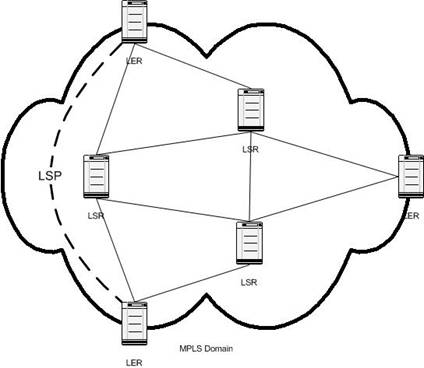
Figure 4 - Typical MPLS network
2.5.5
Label
Distribution Protocol (LDP)
There are two different ways that labels are transported and assigned by
all LERs and LSRs: either (1) downstream or (2) downstream on demand. The
simplest way is to enable OSPF in the backbone and with the help from LDP just
let it distribute possible LSPs to all neighbors. Each LER/LSR opens a
TCP-session on port 646 to its neighbors and exchanges LDP messages [10], and keeps them alive a specified time [2]. When OSPF announces a route change, all LERs and
LSRs rearrange their local forwarding tables accordingly. Each LER then knows
on which LSP to send traffic, for a certain next-hop router.
Another way is to enable BGP-4, and let BGP take care of all route
distribution. The MPLS labels can then be piggybacked on the BGP UPDATE
message. If two adjacent MPLS routers are using BGP, then they can use that for
the label distribution as well [1]. Both BGP and OSPF know the best (lowest cost) way to
each destination, and together with the LDP functions the routers create the
label forwarding tables, and the LSPs needed. There exists a close relationship
between LDP and existing routing protocols.
Even though an understanding of LDP is needed to deploy MPLS in an
existing network, in our case we will examine the implementations provided by Extreme
Networks’ software. The format of the LDP messages is a concern only for the
developers of the MPLS software itself. However, in summary, in one LDP session
between two LSRs/LERs a number of different messages can be sent. They can
contain commands for notification, hello, initialization, keep alive, address
assignment, address withdrawal, label mapping, label request, label abort
request, label withdrawal, and label release [10].
2.5.6 Resource Reservation Protocol with Traffic Engineering
extensions (RSVP-TE)
Another way to actually set up all LSPs, is to make use of Resource
Reservation Protocol with Traffic Engineering extensions (RSVP-TE). Several
different objects are proposed to extend RSVP to make use of intelligent signaling,
so that LSPs are automatically routed away from traffic congestions, network
failures, and similar [22]. Basically it is a protocol that sends out Traffic
Specification (Tspec) objects in the same data path as the actual data, with
requests for different QOS parameters. The signaling done makes sure that all
routers provide requested services to all nodes along a path. It is not another
routing protocol, but it makes use of existing routing tables [2].
2.5.7
The Label
Switching Path (LSP)
The paths established by LDP or RSVP-TE between two LERs can be used for
normal IP-traffic routing, but using the LSP results in potentially higher
speed and only one IP-hop [2]. It is possible though, to make each hop through a
LSR an IP-hop as well, at least in the current ExtremeWare software [2]. This makes the transition to MPLS quite transparent,
and loops can be prevented in case of a configuration or software error. When
only looking at the MPLS label, the speed compared to traditional IP routing is
about the same, because it is designed to operate at line speed anyway. But the
CPU load should lower, because of the simplicity of only looking at the 32-bit
label, thus it is like Ethernet switching.
The paths can also be used to tunnel layer 2 traffic, and these tunnels
are called Transparent LAN Services (TLS) tunnels by ExtremeWare. Using them it
is possible to tunnel VLANs through the backbone network, and still have good
scalability. One problem with the TLS concept is the underlying MPLS
point-to-point transport methodology. One or more VLANs can only be transported
to one other site, i.e. it is not fully meshed, only point-to-point and partly
meshed. One way to solve this is that a VLAN connected to a TLS tunnel can run
in two modes, hub-and-spoke or fully meshed. In the first mode all
traffic received from the local VLAN are flooded into all TLS tunnels (at the
hub-node), and all traffic received from a TLS are flooded onto the local VLAN
and into all other TLS tunnels. At the spoke-sites there is only one local VLAN
and one TLS-tunnel.
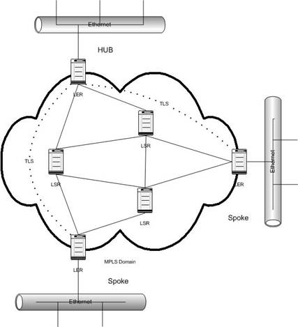
Figure 5 - Hub and spoke
The fully meshed solution does not depend on the hub node. When traffic is received from the local VLAN it is flooded into all TLS tunnels, and when traffic is received from a TLS tunnel it is only flooded onto the local VLAN.
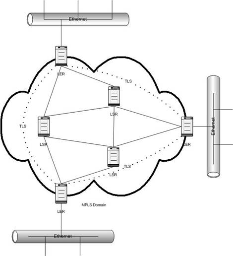
Figure 6 - Fully meshed
This enables all sites to be connected to each other, with slightly smaller overhead as well, compared to the hub and spoke model.
2.5.8
Using
Transparent LAN Services (TLS)
The TLS tunnels in the previous sections are set up with targeted LDP
channels, and they are identified with a VLAN in the ingress LER and the
destination is identified with the egress LER IP-address. This makes it easy to
tunnel one or more VLAN to a specific site, and therefore produce a layer-2
connection through the core network. The frames transported in the tunnel keep all bits except the preamble
and the FCS (it has to be recomputed anyway in the egress switch), including
the 802.1Q VLAN header. The tag will most likely be overwritten in the egress
LER though, so that it matches the egress VLAN tag. This means that it is
possible to tunnel all kinds of layer 2 traffic. If a customer wants to tunnel
more than one VLAN, this has to be solved before the ingress LER in some way.
Only one VLAN tag is allowed, but several TLS-tunnels can be set up between two
LERs, one for each VLAN tag.
2.5.9 The Label Stack
If more than one MPLS
domain exists in a network, a packet may reach a point where MPLS traffic needs
to be tunneled through another MPLS domain. That is where the “Bottom of stack”
bit in the MPLS shim header is needed, when building a stack of labels. The
last label, the label closest to the Network header, has the “Bottom of stack”
bit set to one, in all the other labels this is set to zero. Actually in
Extreme Networks’ solution for Transparent LAN Services a label for the TLS is
first, then a label for the MPLS transport on top of that (i.e. closer to the
Data Link header [10]). Thus there is already a stack of two labels between
the Data link header and the Network header. There is no limit to how many
labels can be stacked together, except that at some point they won’t fit in the
Maximum Transmission Unit (MTU) size of the link frame.
All network hardware
checks the headers in order all the time, including the MPLS headers. First
Layer 2 headers, like the Ethernet Frame, then the first MPLS label. If the
first label is removed because the current router is an egress LER, then it
goes on and checks the next header that can be either another MPLS label or a
layer 3 header, maybe an IPv4 header. If Penultimate Hop Popping (PHP) is used,
then the LSR prior to the egress LER strips off the MPLS label as usual, but
does not insert a new one before the packet is sent to the LER. When the LER
receives the packet, it looks like a normal IP-packet, and can be sent to the
right destination without requiring two lookups. Normally it would first need
to check the MPLS label and then the IP header. But because the last LSR
removed the label and sent the packet to the right LER, it works faster.
2.6
EAPS
–Extreme Networks’ alternative to the Spanning Tree Protocol
2.6.1 Introduction
Due to the drawbacks
of computing a spanning tree [5], especially the time it takes to flip over to other
paths, Extreme Networks has proposed their own standard. They call it Ethernet
Automatic Protection Switching (EAPS), and I have not found much documentation
about it. More info is expected to become available on their website[2]. The only information
currently available is the ExtremWare 6.2 Manual [4] and the technical support at Extreme Networks. It is
similar to other manufacturers’ proposals, which often are called something
similar to “Ring Spanning Trees”.
2.6.2 How it works
The concept is simple.
Check if a connection in a ring is down, and if so, flip over to the other,
secondary interface to let the traffic flow in the other direction in the ring
as well. When running only Extreme Network switches, each node checks if one of
the two ports assigned to the EAPS domain is down. If so, a message is sent to
the master, who carries traffic for the connected VLAN(s) in both directions
and also sends a notice to all the slaves to update their Forwarding Databases.
The change is very quick. In less than a second a flip over is done. That time
is not much dependent of the ring diameter, except that the “down” messages
have to be propagated to the master switch. The time for that is depending on
the media and physical distances, and there is no timeouts that have to be
reached. If not using Extreme’s hardware all the way around a ring, then there
is another check to look for loops. The master sends out hello packets each
second (configurable), and if not received on the secondary interface within 3
seconds (configurable as well) the ring is down somewhere, and the same
procedures as for an open ring are done. More detailed information can be found
in the documentation from Extreme Networks (see above).
2.6.3 Advantages
The major advantage of
EAPS is that it is simple and quickly flips over to secondary paths. A protocol
like EAPS can be seen as the only solution to prevent loops when building a
full layer 2 network, without getting long flip overs. When providing a network
for a video and/or audio stream, a flip over at around 200ms is okay. Over that
it is getting difficult to follow somebody’s talking, and at some point calls
are interrupted depending on the software and the protocols in use.
2.6.4 Disadvantages
There is a risk today
for “super loops”, when more than one ring is established, and a link in common
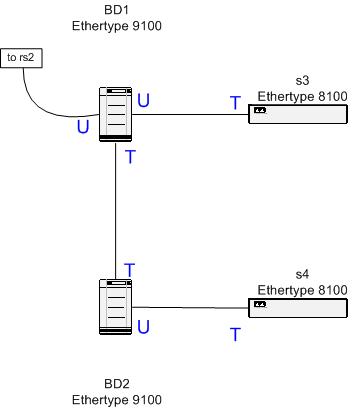
goes down. In Figure 7 there exist two EAPS domains, one to the left and one
to the right. If the middle link goes down, both EAPS domain masters open their
secondary port, and a loop is created, the dotted line. In the normal case, the
traffic in the EAPS domains flows in the direction showed with the big arrows.
Then the masters block them at their secondary ports, the wide large lines. But
when both masters discover that a link is down, the loop is created.
To prevent “super
loops” or to implement EAPS where there exists more than one potential loop,
there has to be one EAPS domain running in each loop, protecting each other. It
will become very complex with just a few loops, why a Spanning Tree Protocol
should be considered.
One other disadvantage
is that EAPS is not a standard. Not all hardware can run this protocol, only
the latest generation of Extreme Network switches with the “Inferno” chipset.
The software is also new, and still a little bit unstable. This will be further
investigated at a later point in the project.
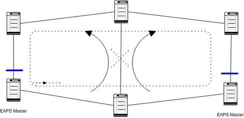
Figure 7 - EAPS Superloop
2.7
The
Spanning Tree Protocol
2.7.1 Introduction
In the EAPS case
above, traffic is transported in protected VLANs, and the blocking of traffic
is only at a VLAN level. The Spanning Tree Protocol was originally defined to
work at a per port basis, but now it is possible to run multiple instances of
Spanning Tree within the same switch, and therefore provide a per VLAN Spanning
Tree domain. There is also work in progress at IEEE extending to their
standards (Rapid reconfiguration (IEEE 802.1w) [21] and Multiple Spanning Trees (IEEE 802.1s)).
2.7.2 How it works
A couple of VLANs can
be added to a Spanning Tree Domain that is only blocking loops at a per domain
level, and not the whole physical port. Such a setup can then provide layer 2
redundancy for added VLANs, with the same characteristics as the traditional
Spanning Trees, with slow flip overs in case of a link failure somewhere. There
exists a feature in new Spanning Tree implementations called “Rapid root
fail-over” which can dramatically lower the time when there exists two similar
uplink paths to the root bridge. In Extreme Network’s case this seems to be a
partial implementation of the Rapid Reconfiguration standard (802.1w) [21].
By configuring a
switch for Per-VLAN spanning tree on some ports and for traditional 802.1d
Spanning Tree Protocol on some other ports, the same Spanning tree can be
distributed to old switches as well as new switches. Of course there are
several restrictions of this in Extreme Networks’ implementation. In general,
the Bridge Protocol Data Units (BPDU’s) are sent with an 802.1Q VLAN tag, and
can then be detected as belonging to a certain Spanning Tree Protocol Domain
(STPD), and they can also be “tunneled” through switches not aware of the new
STP features. I believe this is the solution for a core network where there
exists a lot of potential loops and different traffic VLANs that need
redundancy, and where the ring-driven standards like EAPS won’t work because
it’s too complex. In Extreme Networks’ case of hardware/software the newer
models with the Inferno chipset (“i-models”) with version 6.2.x of the software
are needed, and thus this method will not be possible for the whole network
where older hardware may still exist. However, when building a new network,
that won’t be any problem, except for the cost.
2.7.3 Old versus new
As noted above Extreme
Networks seems to have partly implemented the Rapid Reconfiguration (802.1w)
Spanning Tree Protocol. This means that the functionality with Alternate (Root)
ports is implemented, and a switch can flip over to its alternate root port
immediately if the root port goes down. However, it does not have the Backup
port-facility of 802.1w, where a Designated port has a blocked Backup port to
switch over to. If the Backup port facility would be implemented, a flip-over
in all cases would take no longer than 2-3 seconds, compared to 30-60 seconds [20] in a traditional STPD.
In the current
implementation both new and old switches can participate in the same STPD with
some restrictions. On a link between an old and a new switch, where the new switch’s
port is running in 802.1d-mode, only the protected VLANs belonging to the
current STPD should be added. If not, the STP can block traffic that should be transported on the current
link. If this traffic is blocked, then errors can occur intermittently, which
is hard to discover and solve.
The same kind of error
can exists when running STP and OSPF in the same network, when they don’t agree
on the cost of possible links, therefore blocking traffic in different ways.
However, when running a per VLAN Spanning Tree Protocol this should not be a
problem because only one VLAN is blocked, and each VLAN are assigned a small IP
address range. In case of a link down, all VLANs protected by a Spanning Tree
Protocol Domain are switched over to an alternate path, and all IP traffic,
that are transported on separate link VLANs take another way after OSPF have
found out about the link down. This is why routed traffic should not be
transported on VLANs that are protected by STP. The flip-over is taken care of
by OSPF instead.
3
Layer 3
VPN
As background for this thesis, this chapter
describes the most widely used layer 3 VPN today. It may be used by a customer
to achieve more security on top of a Layer 2 VPN, or only as a way to transport
IP traffic securely over the Internet.
3.1
IPSec
Today it seems like most VPNs are slow and/or
expensive services based on layer 3 solutions. Hardware implementations are
usually part of a firewall, placed at the customer’s premises. Traffic is
routed through these boxes, and the ISP’s network transports the traffic
according to normal rules for layer 3 traffic. This enables different offices
of a customer to send traffic, for an example web and telnet-based traffic,
with high security over external networks, for example, via an ISP. IPSec[9] uses a combination of asymmetric and symmetric
encryption, which makes sure that the connection is secure by validating the
two ends of a tunnel, ensuring that the content is not changed, and that nobody
listening to the traffic can understand it.
It is also possible to create VPNs between a
specific workstation and a network, or between two workstations connected to
the Internet. However, since our focus is on traffic over the backbone, we will
not further examine these cases.
3.2
Advantages
IPSec is a wide spread standard and it works
well. When IPv6 is introduced, IPSec is going to be even more wide spread, as
it is a mandatory part of IPv6 and hence will be built in everywhere. In the
IPv6 standard a number of optional headers can be appended to the basic IP
header, and one of them is the Authentication Header and an other is the
Encapsulating security payload header. These two Extension headers carry
information about authentication and encryption when IPSec is enabled. Today one
can run IPSec over IPv4, and software is available for both point-to-point,
point-to-network, and network-to-network applications for a lot of platforms [9].
3.3
Disadvantages
One of the major drawbacks of IPSec is the
additional knowledge and cost for the customer to buy and configure these
boxes. In addition, the additional security achieved may not be needed, because
it’s a layer 3 solution, and other methods, like SSL[3] and SSH[4] may
already be used at higher layers. It would be much easier if a customer could
simply plug his Ethernet switches into his Internet Service Provider at
separate secure locations, and without any configuration whatsoever be able to
run his applications securely across the network. This was the impetus for introducing a layer 2 VPN.
Another drawback of IPSec is the difficulty of
running at link speed. Although the VPN boxes can be very fast, they are
generally not fast enough for the rapidly increasing link speeds. This is
especially true when trying to implement a cost effective solution [14]. As encryption always takes some time, if it is not
done directly in special hardware, it can take a lot of time thus substantially
increasing network delay.
4
How to
build a Layer 2 VPN
In this chapter three
ways of building a Layer 2 VPN are presented, with enough detail that we can
determine if they satisfy our goals. Some results from testing will also be
reported. In section 4.4 a comparison of all of them are done, together with
details of why. We have selected one of these as the best method to meet our
goals.
In the sections below
I have separated the network into the core (or backbone) network, and the
distribution network. Usually service providers like Arrowhead have built up a
complete core of high capacity links, which are of high importance and shared
by both the service provider and its customers. When services are sold,
distribution networks are built from the core towards the customer. A
distribution network is usually located within a city, and is shared by the
customers there.
4.1
Implementing
a Layer 2 VPN with VLANs
4.1.1 Overview
The first way of
providing a Layer 2 VPN that meets the requirements listed in section 2.2 is to provide the customer with an untagged VLAN via
a port of the closest access switch. This VLAN has to have a unique 802.1Q VLAN
tag for the transport in the network, and must be added to all switches between
the two (or more) access switches the customer is connected to. This works
today with existing hardware, as long as each switch supports 802.1Q VLAN
tagging. The problems here are that it will become very complex after a while
to provide redundancy and to keep track of all VLAN tags. The hardware in use
can only hold 3000 tags (in the core) and only 255 tags at the access point.
According to my calculations, it should be possible to have as much as 2500
customers with a Layer 2 VPN service from one city to other cities in the
country, and that the “hub” city will probably be
Another problem is to
configure this VLAN on ALL switches involved in connecting the two endpoints of
a VPN. This means, creating the VLAN, giving it a tag, and add it to the right
ports of all the intermediate switches. Both the work doing this and not
forgetting any switch are problematic. This configuration problem may be solved
with configuration software, which is discussed in section 4.1.4.
4.1.2
How to
solve redundancy problems
To be able to provide
full redundancy from one access switch to another, the customer’s VLAN has to
be configured on at least two disjoint paths, i.e. no link on the way can be a
single point of failure. In a typical network, see Figure
8, a customer connected to the righter most switch (S1) wants full redundancy to another similar
network in another city.
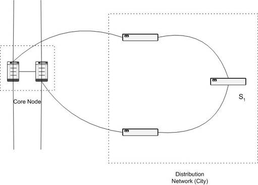
Figure 8 - Typical distribution network
If the distribution network is as simple as in Figure 8 the best solution is to run EAPS. However, I believe it becomes too complex to run EAPS if there is more than one layer 2 loop, and in that case I would suggest running a per-VLAN Spanning Tree Domain instead. But when running a simple network like the one above, an EAPS domain containing both the core switches and all three distribution switches is the best (and simplest) solution. The more difficult problem is how to provide redundancy from the core switches, located in a safe location, to the other egress point of the current VLAN. Even though my tests of the new per-VLAN Spanning Tree Protocol were successful, and it proved to work exactly as expected and as desired, it feels a little bit awkward to enable a full spanning tree domain in a core containing hundreds of switches like the ones to the left in Figure 8. A typical core node contains two switches with an interconnection in between, and four links to two other similar core nodes. All these switches are routing IP traffic as well, and the network works perfectly well for all layer 3 services provided, but it’s a little bit more difficult to take advantage of the design for a layer 2 service. If when enabling a Spanning Tree in that web of links, there should exist more than one place where the number of bridges to the root bridge exceeds the maximum recommended number of switches seven [4], then there will be problems due to the time it will take to calculate a new spanning tree when one link somewhere goes down. With the new partial implementation of the Rapid Reconfiguration Spanning Tree Protocol the first flip-over is quick, but the restoration of the tree will take the normal time when the bridges have to be in LISTENING and LEARNING state, i.e. about 20-30 seconds. This will not have any impact on the Layer 3 traffic, but all VLANs belonging to the current Spanning Tree Domain will be temporary down until the new Spanning Tree is computed.
To overcome the problems with such large Spanning Trees, I think a simpler approach where there exists one single point of failure may be enough to begin with, if we can accept one. If only one of the core switches in Figure 8 sends the VLAN to the other core nodes, and therefore only one of the two parallel paths are running the Layer 2 services, the Spanning Tree may be of a more limited size. In such case an EAPS domain may be possible instead, at least in some parts of the core where a separate ring can be distinguished. If a core switch in transit goes down, there always exists a way around one of the core rings, but if the core switch transporting the VLAN out to a distribution network goes down, the service is down. A temporary solution to this is to enable the VLANs on the other path around this switch. In all cases, all core switches must be up and running all the time, with very high availability.
By solving this, full redundancy can be delivered to the customer. However, there exists places where there is only one way out from an access switch to the core, then in such case, no redundancy from the service provider’s point of view can be provided.
4.1.3
Service
management
As noted above the
correct configuration of the switches are essential. Configuration needs to
take place at all switches between two access points, and also on a redundant
path if that is to be provided. Configuration is done via a Command Line
Interface (CLI), through a SSH/telnet session to each switch. Most hardware
suppliers have some kind of software to allow remote configure via Simple
Network Management Protocol (SNMP). However, some tasks have to be done through
a CLI anyway. An easy integration with existing monitoring and inventory
database may be desired. This gave me an opportunity to create a flow-through
system.
Other issues of
service management include being able to monitor the service in order to see
that the agreed service level is provided. The software developed (next
sub-section) provides information about which VLANs are affected when a switch
is down, and based on this the customers involved are listed. However, it is
difficult to really see if traffic actually can be sent through a VPN, without
being on the same VLAN. Therefore although it is possible to see that a given
VLAN should be up, to see if the customer can actually send his traffic some
kind of device has to be connected to his endpoints and for this existing Layer
3 monitoring methods are used.
To be able to change the speed of the VPN the Quality
of Service profiles in the relevant access switches has to be changed. With the
hardware/software used today, it is possible to make this available through a
web interface to the customer, which generates a request to the support. With
other bandwidth limiting products specially made for this it may be possible to
automate this, but more hardware would be needed. I believe that there is not
much need for a customer to change his bandwidth by himself, even if it’s
possible to account for the changed bandwidth. Although some people would like
to be able to make rapid changes in the bandwidth provided, but I think that
the additional hardware/software needed for that, together with few customers
buying large amounts of bandwidth, make the whole idea not profitable. Too many
customers may decrease their bandwidth in order to save money.
If we only have four
Quality Of Service (QOS) profiles, as in the case with the Extreme Networks
Summit 24 switch, a number of bandwidths are possible to provide without the
special solutions discussed above. In Table 1 a summary of the available link speeds are provided.
Each QOS Profile is configured with a percentage of the current port speed, and
therefore the number of different speeds is eight.
|
Suggested QOS Profile
Percentage |
10
Mb/s port speed |
100
Mb/s port speed |
|
20% |
2 Mb/s |
20 Mb/s |
|
50% |
5 Mb/s |
50 Mb/s |
|
80% |
8 Mb/s |
80 Mb/s |
|
100% |
10 Mb/s |
100 Mb/s |
Table 1 - Possible speed
configurations
4.1.4
VLAN
Tracking software
One task in this
project was to design and implement the configuration management system. The
software developed has the following features:
- Create a new
VLAN in the system
- Take a list
of switches and find an unique tag for use on these switches
- Provide the
engineer with telnet scripts to implement this configuration
- Keep track of
all VLAN names and tags
- Find all
VLANs configured on one switch
- Find all
switches configured for a VLAN
- Add/Delete
switches from a VLAN
- Merge two
VLANs
- Change the
tag for a VLAN
- List the
status for switches providing VLANs, to see if any limits are reached
(i.e., to see that the number of VLANs in the switch will not be exceeded)
All these functions
are provided via a web interface. To ensure that the actual configuration of
the switches is as believed, an automatic check is made each night and the
difference required updating the database to match reality are stored in the
database to be committed by the first user using the system the next day. There
is no simple way of configuring the switches directly from this management
system, this is why telnet-scripts are generated and the daily comparison is
done. It is usually also a good idea not to give a system total control of
something as important as this. If a configuration session is aborted, or the
database is corrupted, connectivity may be lost to equipment out in the country.
Another advantage with
this software is the simplicity of optimizing the tagging. One example is that
all the link-VLANs connecting each Layer 3 router use unique tags. They should
be able to share 5-10 VLAN tags in the whole network. With this software a
change of tags is simple, and the change can be done for each link-VLAN. With
this change, more customer VLANs can be configured in the core.
For more details, see
Appendix E.
4.1.5
Solution
to provide customer tagging
One big disadvantage
with the Extreme Networks’ implementation of VLAN-tunneling, VMAN, is that a
switch running in “VMAN-mode” cannot modify the traffic inside a VMAN in any
way. Thus it is not possible to mix VLAN tagging with the VMAN tagging. If
running VLAN in the core, a customer has to send his traffic in one VLAN, untagged on a port towards
the provider. A lot of Service Providers and large companies need to send their
own VLAN tagged traffic through a Layer 2 VPN. I have found a solution that
works with Extreme Networks hardware. When a switch receives traffic with
Ethertype 9100 (the Ethertype used for VMANs) on a port configured only to
receive untagged 802.1Q VLAN traffic, the VMANs received on that port are
tunneled in one VLAN. Consider that this happens in the left most switch in the
distribution network in Figure 9. That switch adds another 802.1Q tag before the VMAN
header in the Ethernet frame, and therefore the traffic can traverse to the
other VMAN Switch. If the traffic received on the left distribution switch’s
untagged port is 802.1Q tagged traffic with Ethertype 8100 it is simply thrown
away, but if it is unknown traffic, it is treated as untagged traffic, and can
therefore be tunneled.
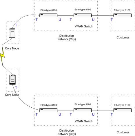
Figure 9 - VMAN in VLAN
The cost for this is one more switch on each path. The Service Provider either provides this switch or the customer does so himself. In the later case the idea is sold instead. Another disadvantage is the problem of managing this VMAN Switch. There is no way to connect to it via a VLAN in the core, since we can not send untagged traffic from the core to a dedicated port configured to receive untagged traffic on the VMAN switch! That requires using another port and fibre, or if placed in the same location, just another patch cable to connect to a management port of the VMAN switch. It is also a little bit more expensive to provide redundancy, because there is now one more single point of failure, the VMAN Switch.
Note that if the Service Provider controls the VMAN-switch, then other customers can share that switch if they also need their own VMAN between the same endpoints. The problem is that the second customer needs to have fibres to the same locations as the first customer, which may not be easy or inexpensive.
4.1.6
Security
When providing a Layer
2 VPN service, the security expectation has to be clearly defined, as noted in
section 2.1. Unlike a Layer 3 VPN where there are boxes
encrypting the data as specified via IPSec, there are no boxes to encrypt layer
2 payload. Thus using a sniffer we could listen to another VLAN, because they
exist on the same physical link. According to Extreme Networks’ technical
support there are two ways to actually handle VLAN tags in the switches, and
they are using the secure one. This prohibits users from manipulating the
frames on the wire, so that there is no way to forge the frames to belong to
another VLAN if the tag is known.
So, there is no way to
listen to the customer traffic, and there is also no way to insert traffic
without being discovered. The only possibility I see is to access our switches
and insert hardware between them. Another risk I see is that if somebody
misconfigures the VLAN on more than the specified switches/ports in error, some
broadcast traffic can be read. Then if somebody acts as if they are on one of
the two links using the other party’s MAC address, he can receive the traffic
and also insert other traffic. With secure configuration routines and a very
high level of security required to access the configuration of the switches,
these kinds of errors can be avoided, and the layer 2 VPN can be seen as a
private network compared with traditional techniques as Frame Relay and ATM
Virtual Circuits. Usually higher layer encryption, like IPSec, is used on top
of all these as well.
4.1.7 Summary
A service based on
VLANs only is possible to provide today. There exists problems, such as the
redundancy and configuration complexities, but it is possible to overcome them.
Although it can be a low cost solution, to start with, the scalability is poor.
After a couple of thousand customers, around 2500 different occupied tags in
any switch, another solution has to take over. However, it is a solution that
can run on several hardware platforms, without too many incompatibility
problems. VLAN tagging according to the IEEE 802.1Q standard is wide spread,
but there is always some kind of extra functionality when using only one
supplier of hardware, as well as management simplicity and cheaper purchase.
4.2
Implementing
a Layer 2 VPN with both VMANs and VLANs
4.2.1 Overview
Continuing the
discussion about the technique in section 2.4.4, a backbone built for VLAN tunneling in VMAN can be
very tricky. There are some drawbacks with Extreme Networks implementation,
especially when migrating from an existing backbone design. Building a backbone
from the beginning and how to use these techniques in existing network are
dealt with in parallel in the following sections.
4.2.2 Design of the core
Because of the fact
that a given switch cannot run both VLAN and VMAN software at the same time,
there has to be a border between the two domains. The first approach is to
build a core completely built of VMAN enabled switches. In all the core
switches there has to be one port for each VMAN that has to be terminated in a
switch next to the core switch, and therefore also one switch for each VMAN,
right outside the core. One of the VMANs may be the VMAN containing VLANs where
Layer 3 traffic from all customers are transported, and another may be a
customer’s Layer 2 VPN in which he can use his own tagging. That leaves maybe
one or two VMANs left for Layer 2 VPN tunneling in one VLAN each. Because of
the distribution of all VMANs everywhere, at first this approach sounds very
expensive both in data transmitted to unnecessary places and in extra hardware.
Besides the customer
traffic, there has to be some way to manage the switches in the core. This
cannot be achieved with normal SNMP or telnet/ssh as of today, because the
switches are not reachable from outside the core, except by having an extra
link connecting one of the VMAN switches with a switch from the outside, both
with untagged ports. By doing this, one or more back doors into the core can be
established, preferably at least two in different parts of the network. Network
engineers feel a little bit awkward limiting the access points in this way,
especially when most switches have to be remote manageable because many of them
are located in vaults out in the country.
4.2.3 Design of the distribution network
Close to the design of
the core is the design of the adjacent distribution network. It is not that
hard to build a VMAN/VLAN network only, but it has to handle the Layer 3
traffic as well. In the distribution network both Layer 3 traffic and the Layer
2 VPN traffic have to share the same links and the same switches/routers, or
maybe to transport all IP traffic to one of the core switches/routers in a
VLAN, to be routed there. If running VMAN in the core, that is not possible. It
is not possible to route the traffic in the core, which is desired. If not
routing in the core, all traffic has to be transported out from the core to be
routed, to find the best ways to the exit points from the service provider. Too
much traffic is transported too far before routing, so that redundancy is lost,
and utilization becomes poor.
If only providing a
Layer 2 service, without full redundancy, a network as shown in Figure 10 can be used (for Customer A, where the other endpoint
is similar, but outside the figure). That is the first approach, which is easy
to provide as the beginning of a migration from an existing design. When redundancy
is needed, it can be built as shown for Customer B. Note that there must be
more than one distribution network ring, one for each VMAN. One of the major
advantages of 802.1Q VLAN tagging is that more than one LAN can share physical
links and switches. This is not possible if running VMANs, where each VMAN
needs to have its own sub-network.
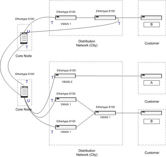
Figure 10 - VMAN in the Core
4.2.4
Redundancy
When building VMAN
rings as discussed above, the cost of redundancy is the same as before, except
that there is a multiplier based on how many VMANs there are. In the core
either EAPS or a Spanning Tree Protocol Domain is needed, to protect the VMANs
transported. When coming to a core node where the VMAN is to be terminated in
the VLAN switches, there are several ways of providing redundancy. In Figure 10 there are two physical links from one core node, the
single point of failure, to each part of a distribution network. This has same
simplicity as in the VLAN tunneling case in section 4.1, where a simple start to implement this in the core
is desired. In this way only one of the usually two core switches are involved.
One other way is to
let the distribution ring be connected to the core at two core switches. By
doing that the complexity of the Spanning Tree Protocol Domain needed in the
core increases dramatically.
In either case,
redundancy for the VMAN may be provided, but providing redundancy at a VLAN
level is much more difficult. The core switches don’t know about the VLANs
inside the VMANs, thus the distribution network creates loops. The distribution
networks needs to run as one big Spanning Tree Domain, which seems not to be a
good solution. If running a per-VLAN spanning tree algorithm, the core switches
will transport the BPDUs without any problem in theory. I have not been able to
test this, and that should be done before trying to implement a Layer 2 VPN
based on VMANs in the core. The loops in the distribution networks are like the
ones in Figure 11, where the Ethernet trunk is the VMAN core, providing
redundancy for the LAN segment, and the outside loops are the distribution
networks in separate cities.

Figure 11 -
In summary, the redundancy has to be solved in two levels; the VMAN core running EAPS or preferably a STPD, and the distribution network domain where one STPD is needed for each VMAN, spread out over all cities running that VMAN. Because of all disadvantages with VMANs I have not been gone much further with this solution. VMANs are not a good solution realizing Layer 2 VPNs.
4.2.5 Service management
When running VMANs
there has to be an even more intelligent tracking system and service management
than for the Layer 2 VPN using only VLANs. In section 4.1.3 all basic issues can be found, but there are a couple
of additional issues. Tracking software also needs to keep track of in which
VMAN the specified VLAN is transported. In some way there is also a need for
checking how much traffic is transported to unwanted destinations, and when a
solution where a VMAN is split up into two VMANs is a better solution
economically (if possible). This is a huge puzzle to cope
with, finding ways of delivering a VLAN from one point in a city to some other
point in some other city. The same VMAN needs to be terminated in both cities,
and distributed to the right locations. It seems like a very expensive and
complex solution.
4.2.6
Customer
tagging
When possible, one
whole VMAN can be delivered to a customer, and he or she can then run his own
802.1Q tagging, and untagged data as well. The only thing needed is a port in a
VMAN enabled switch, which could be the case for Customer A in Figure 10 if the switch he is connected to is running Ethertype
9100 instead.
4.2.7 Security
The security in VMANs
is exactly the same as for the Layer 2 VPN solution using VLANs only, see
section 4.1.6.
4.3
Implementing
a Layer 2 VPN with MPLS
4.3.1 Overview
Technically the newest
and most expensive solution seems to be MPLS. One can see this thesis as a way
of trying to find another solution that will meet the requirements, because it
seems like MPLS solves most of the problems discussed so far. The major
drawback, as noted already, is the cost. It’s very expensive to implement MPLS,
but it can be done in several steps. I have suggested upgrading to MPLS in
three steps; first implementing it in five strategically placed core nodes, and
then upgrade one core node at a time until all of them are running MPLS, and
finally implement it in the distribution network as well.
4.3.2 Design of the network
Most people think the
best way to make use of MPLS is to implement it everywhere, from the customer
access point to the very middle of the core. However, a feasible approach for a
service provider is to only run MPLS in the core.
I believe the main reasons for this are:
·
The cost
would be lower
·
Knowledge
about MPLS is only needed in the team maintaining the core due to the smaller
number of devices running MPLS
·
Transition
from a Layer 2 VPN solution using VLAN only is simple
·
If using
equipment from Extreme Networks, only hardware made for the core needs to be
enabled (the Black Diamond switch)
·
The number
of LSPs needed (every point need to have a LSP to each other point) would very
large. The amount of LSPs needed is n*(n-1), where n is the number of MPLS
enables switches. The scalability of this is yet
unknown, but the label space in one MPLS domain allows around 1000 switches due
to the 20-bit label (![]() ).
).
When looking at how to
design the core for MPLS it seems like not much have to be done. When upgrading
a core switch to MPLS, the same configuration can be run initially on that
switch, and then additional configuration is made for MPLS. In that way all
previously provided services at that node are intact. This is not true today
because the 6.2.x release of the ExtremeWare software does not support MPLS
yet, but it is in use because of that particular version’s additional features
like per-VLAN spanning tree.
To be able to enable
MPLS, a link-VLAN has to be set up between two MPLS switches. The VLAN must
have a small IP-network assigned, and be added to the same OSPF area as all
other MPLS switches. It is possible to have more than one OSPF area, but then
it will be one MPLS domain for each OSPF area. Furthermore, no IP-only hop can
exist between two MPLS-nodes, and if there are Layer 2 hops between the MPLS
switches, the time it takes to discover a link down and rearrange the LSPs will
be much longer. Currently the OSPF timers are controlling this. This makes the
“stage 1” MPLS implementation slower in detecting link errors.
Once MPLS are
implemented in the core, the Layer 2 VPNs can be created using the Transparent
LAN Services (TLS). From each access point to the closest MPLS node, a Layer 2
VPN like the ones in section 4.1 is needed. Then a TLS is set up to the MPLS node
closest to the second location of the customer. The VLAN tagging does not have
to be unique across the MPLS domain; the egress LER overwrites the tag with the
egress VLAN tag anyway, identified with the VLAN name only. The name should be
unique, which makes it much easier to manage.
One way to tunnel the
link VLANs used for MPLS may be to use L2TPv3 between two routers, and normal
VLANs to those routers from the LSRs. I don’t think it will scale well without
spending a lot of money. But if it’s very important to reach some point only
reachable via IP it is one solution. It is also a more or less a temporary
solution, due to the mix of tunneling techniques and the extra overhead. The
technique is already available in Cisco routers, even though it’s still a
draft.
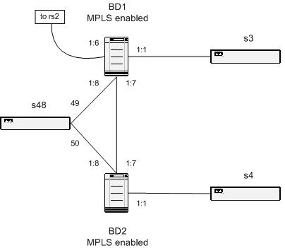
4.3.3 Redundancy
To provide redundancy
in the core, each MPLS switch should be located so that it has at least two
separate VLANs terminating at other MPLS switches. It is wise to plan for this,
so that there is no bottleneck after only a few Layer 2 VPNs are sold. We also
have to remember that the maximum throughput of one MPLS add-on card to the
Extreme Networks’ Black Diamond switch is 4Gbit/s, and that a maximum of four
cards can cooperate within the same switch.
Furthermore, to
provide redundancy in the border between the MPLS core and the distribution
network, two links are needed. Again it can be compared to the case where
providing a Layer 2 VPN with VMAN in the core, see section 4.2.4. The MPLS switches should run in meshed mode for the
TLS tunnels that need to terminate in more than two points, and the
distribution network outside the MPLS domain needs to run a per-VLAN Spanning
Tree or EAPS. If it is not possible for some reason to run a per-VLAN Spanning
Tree the redundancy has to be handled manually. This only applies to the
distribution network, because the redundancy issues in the MPLS-core are
handled automatically by MPLS.
4.3.4 Service management
To be able to set up a
Layer 2 VPN with MPLS in the core, several steps have to be taken. First the
same procedures as for the Layer 2 VPN with VLAN have to be done for each
end-point (region) of the VPN, as in section 4.1.3. Note again that there is no need for a completely
unique VLAN tag; they must only be unique per region.
There are two ways of
enabling MPLS in the core, when running the current software from Extreme Networks;
normal LDP and RSVP-TE. The MPLS link-VLANs are added to the MPLS domain with
one or both of these methods. They both involve creating LSPs to other MPLS
nodes. The LDP method is automatic and the default, and is enough to use in an
IP transporting mode. RSVP-TE seems to be better suited for VLAN tunneling,
because you can set priorities and bandwidth limits for each LSP. This is the
area where the most benefits of MPLS can be found. In a typical MPLS network
LDP created LSPs are used for IP-traffic and RSVP-TE created LSPs are used for
TLSs. The drawback with choosing RSVP-TE based LSPs is that you have to create
all the LSPs manually, with a couple of extra lines of configuration per LSP.
If limiting the bandwidth in the access point, i.e. as close to the customer as
possible, this is unnecessary and LDP created LSPs can be used for all
services.
So, when the ingress
and egress VLAN are configured, the TLS needs to be configured as well. If
running LDP established LSPs, only one line in the CLI is needed, otherwise a
few more lines are needed. Today there is no other way of configuring this, but
there is work in progress to automate the configuration and management of TLS,
according to Extreme Networks homepage[5]. To implement this both
support in the software of every switch and in the management software suite is
needed.
If running MPLS only
to make use of its capabilities of tunneling VLAN, then there is not much more
service management than this. If also enabling IP routing through the MPLS
cloud, which is the default, care must be taken about the possible bottlenecks
and longer fail-over times when OSPF timers are timing out instead of switches
in the OSPF area discovering link failure. This is the case when there is more
than one layer 2 hop for a point-to-point IP link.
All VLANs created for
a customer, and LSPs if created LSPs manually with RSVP-TE, should be named
according to an agreed standard for connection numbers (Swedish.
förbindelsenummer) so that trouble shooting and network management can take
place. Today there is no link between the MPLS setup and the customer
databases, thus the routines for keep track of this must be better than the
usual administrative routines.
4.3.5 Customer tagging
The Layer 2 VPN
provided by a MPLS core cannot carry customer tagged VLANs. Each TLS created
can only contain one VLAN. The traffic has to be received from a customer on an
untagged port in the closest access switch, and if the customer needs to send
more than one VLAN he or she has to either buy more than one VPN, or utilize
the same techniques for VMAN tunneling in a VLAN as presented in section 4.1.5.
If the MPLS-core is
also running VMAN, a combination of the Layer 2 VPN with VMAN and with MPLS can
be provided, and therefore provide customer tagging in the same way. According
to the specifications there should be no problem having the MPLS-switches run
in VMAN mode instead of VLAN node, with all the advantages and disadvantages
already discussed. I have not been able to test it though, and it does not seem
to solve any problems, but only creates new ones.
4.3.6 Security
Due to the fact that
the current MPLS implementation from Extreme Networks is not configurable
remotely, except from the normal CLI, the chance of making a configuration error
is small. No software can by mistake configure the MPLS part in error. On the
other hand, it is more complex; hence the persons who are trusted to configure
MPLS have to know what they are doing.
Furthermore, the
number of steps and their complexity to create a Layer 2 VPN based on MPLS are
greater than for other VPNs, which make the risk for a misconfiguration
greater. It seems as if a misconfiguration is the only way that a Layer 2 VPN
can be insecure, as discussed already in section 4.1.6. That’s why a lot of attention is needed to the
configuration routines.
4.3.7
Summary
When running the
expensive MPLS solution, a valuable service can be provided. It is easy to
provide redundancy in the core, good scalability in the number of VLANs
possible to provide, and using a developing technique, which can lead to even
more advantages than discussed in this report. There is a lot of work in
progress to smoothly enable Layer 3 VPNs through a MPLS cloud, with close
relation to iBGP and IPSec[7][6]. When that is stable and available, greater use for a
MPLS network is likely. I believe that most of these applications need
MPLS-enabled hardware in the access-point to each customer.
There are few limits
to a MPLS solution. When implemented everywhere in the core, the number of
VLANs available to the distribution network of a MPLS node are close to 3000.
To increase that number a separate distribution network can be built next to
the existing one. In such a case there should be profitable enough to do that,
and it may also be necessary to add to the network with regards to the amount
of traffic in the existing network. The MPLS domain can handle more tunnels
than VLANs, as long as each LER only terminates less than 3000 VLANs.
4.4
Comparison
I have chosen the
Layer 2 VPN with MPLS as the ultimate solution for realizing Layer 2 VPNs. To
start with I think the first solution, Layer 2 VPN with VLAN, is a good start,
but then MPLS is the best way to go in the long run. It is also a natural way,
because VLANs are a part of the MPLS solution. It is more a question of when to
start with MPLS.
The reasons for
choosing MPLS are all the capabilities and interesting features available, and
of course the way redundancy is
solved in the core. Traffic is automatically transmitted only on one path in
the core when running MPLS, and with several secondary paths available
“pre-configured”. The traffic is not flooded to places where it is not needed,
as in the VMAN and VLAN cases. The redundancy in the distribution networks are
similar in all cases, except in the future where MPLS may be implemented all
the way to the access point. The distribution networks have to be designed as
rings, and scaled for the necessary that traffic as well. All traffic is
flooded all the way around the ring, except where the Spanning Tree Protocol
blocks one link somewhere in the ring.
The way a VPN is
configured is getting more complex the more advanced the techniques are. When
running a Layer 2 VPN with VLANs they have to be configured at a large number
of switches, although with VMANs it may be a little bit simpler, if a VPN is
already configured with the same end-points. If not, the setup can be far more
complex, as noted in previous sections. Creating MPLS based VPNs include more
steps, but they are not much more complex than the other cases. The
configurations in the distribution network are similar, but in the core only
the egress and ingress switches need configuration. The possibility to monitor
the services is similar for all variants of VPNs. It’s not easy to see if any
of them work with current software, but they are all using the same techniques
in the endpoints, VLANs. If running MPLS in the core, with dedicated TLS
tunnels as suggested, there are counters to check if traffic is flowing in both
directions. If using dedicated ports in the access switches for the VPNs, as
suggested to provide better security, it is also possible to monitor the
counters, but you cannot be sure that they correspond to “successfully
transferred bytes” via the VPN.
One of the goals for
this thesis was to find a solution that would not be unnecessary expensive.
I have not made any exact calculations, but it’s clear that the MPLS solution
is the most expensive alternative, at least initially. There is a large cost to
enable MPLS in the core, but it may become profitable quite fast. The cheapest
alternative should be the first VLAN solution, but because of poor scalability
it would be impossible to continue using that solution. Finally the VMAN
solution, which I see as the worst solution. The number of VLANs possible to
run does not expand that much, because only a few VMANs can be run in the core.
The cost is also quite high initially, mostly because of all extra hardware
needed. It’s not a nice solution considered how the network has to be built,
and scalability is not as nice as in the MPLS solution. When one VMAN is
nearly full, another one has to be set up, with corresponding extra hardware
required at each core node and a distribution network that will cost a lot of
money.
All solutions can
provide untagged VLANs to the customer, but only the VMAN solution can, when
running VMAN close to the customer, provide customer tagging. It may be a
business strategy to buy another switch and let the customer tag his own
traffic for the other two solutions as well, as noted in section 4.1.5, but the Layer 2 VPN itself cannot tunnel tagged
traffic transparently.
4.4.1 Transition to MPLS
A noted above, the
natural way to implement this is to go from a fairly simple VLAN solution to a
solution with MPLS in the core. There is no need to do any reconfiguration in
the distribution network, and you only have to remove the VLAN from all core
switches except the MPLS ingress and egress LERs, and then create the TLS
tunnel. There is a short downtime when doing this; therefore it should be done
in a scheduled service period during low traffic hours. The core switches
running MPLS can be set up, configured and tested before the VPNs are
transferred to them, thus a transition should be very simple to create.
5
Conclusions
5.1
Conclusion
During this project I
have discovered several disadvantages with all techniques, which made a
realistic and fast implementation impossible. My hope was that the MPLS
solution was not as expensive as it turns out to be, and that the VMAN solution
would be usable in an Extreme Networks’ network.
In any case, my
knowledge in this area has increased a lot, and my work has been useful both
for me and for Arrowhead. It always takes more time than expected to actually
get things done, such as selling the VPN services to customers. But VPNs are
old today, and when the sales department has finished the product
specifications, I think that this is going to be a large and interesting
service.
Sometimes it feels
like a political decision to implement MPLS, but I think it’s the only way to
go with a Gigabit Ethernet backbone. The Layer 2 VPNs implemented with VLANs
are the first and best choice with such a backbone, followed by an upgrade to
MPLS in the core, and finally adding MPLS in the distribution networks as well.
I think Extreme Networks’ MPLS implementation is ready for implementation.
However, new software releases are received quite often, and problems will most
likely occur.
The testing I did was
a success. All techniques worked as expected, especially the per-VLAN Spanning
Tree Protocol. A lot of solutions in this report need the per-VLAN STPD, and
also the rapid convergence of this protocol, so it is very important to follow
up the implementation of this. Some of the ideas, configurations, and results
of my testing can be found in the appendices.
One thing that I have left out this report is
the evaluation of other manufactures products. I have only read about other
equipment. To make this project more complete, some more research should be
done regarding other manufacturers products, but the same methods are most
likely to be used by these other vendors. Cisco got their 802.1Q encapsulation,
often referred to QinQ, and Siemens have something called Shared VLAN (S-VLAN)
in their ERX switch. According to Siemens technical support they are using
Ethertype 9200 instead of 9100, but they can put S-VLANs and VLANs on the same
physical port. This will most likely make the VMAN solution more useful.
5.2
Future
work
A very interesting issue is to investigate all
traffic that will be transmitted in the core when running large broadcast
domains. Next specific activity to do is an extensive traffic analysis of the
traffic when running national VMAN and VLAN in the core. How much traffic is
broadcast when running a point-to-point Layer 2 VPN? How much when running
multipoint? This can be an important issue, because all traffic may be
transported all around the ring, both on primary and secondary (backup) paths.
Because this will always fill up the links with the traffic, if a link goes
down, there are no worries about the capacity for all of the traffic.
Furthermore, a way of monitor the VLANs, to see
if they actually are up, would be nice to have. Investigations of managing the
VLANs both with new techniques and with existing software are necessary. The
problems are caused because we cannot inject traffic in the VPN without
violating the standards and the agreements concerning privacy.
It might also be a good idea to develop a
solution using L2TPv3 or similar, as discussed in section 2.3, for use when only IP connectivity is available to a
customer. This seems like a solution that does not scale well, but it may be
sufficient. Personally, I think that it is a solution that customers can manage
by themselves, but it may be something to earn money from. Perhaps combining a
common firewall with a L2TPv3 solution in the same box, using Linux, would be a
good approach. This will enable customer tunnels using other service providers’
networks, which can be useful. There is also work in progress concerning
exchanging MPLS-labeled traffic between service providers, which enables the
same thing.
When a complete MPLS network is implemented,
more services like the BGP MPLS VPN described in RFC 2547[7] should be investigated and implemented. That will
make use of the network better, and IPSec may be implemented as well according
to the draft-ietf-ppvpn-ipsec-2547[8]. This will enable a secure layer 3 VPN, which may
replace the existing solution built on customer provided equipment as sold
today.
6
References
[1]
Extreme
Networks, Leveraging MPLS to enhance network transport capabilities
http://www.extremenetworks.com/technology/whitepapers/MPLS.asp
Accessed on 2002-01-15.
[2]
Extreme
Networks, MPLS Installation and User Guide
http://www.extremenetworks.com/support/documentation/MPLSInstall.pdf
Accessed on 2002-02-01
[3]
Extreme
Networks, Tech Brief Extreme Networks VMAN
http://www.extremenetworks.com/technology/whitepapers/vMAN.asp
Accessed on 2002-02-04
[4]
Extreme
Networks, ExtremeWare Manual 6.2
http://www.extremenetworks.com/support/TechnicalDocumentationSoftware.asp
[5]
Bay
Networks, Spanning Tree Algorithm
http://support.baynetworks.com/library/tpubs/html/router/soft1000/bridge/2950A-19.html
Accessed on 2002-01-15.
[6]
I.
Pepelnjak and J. Guichard, MPLS and VPN Architecture, Cisco Press,
[7]
E. Rosen
and Y. Rekhter, BGP/MPLS VPNs, RFC 2547, 1999
[8]
E. Rosen
et al. Use of PE-PE IPsec in RFC2547 VPNs
http://www.ietf.org/internet-drafts/draft-ietf-ppvpn-ipsec-2547-01.txt
Accessed on 2002-05-15
[9]
C. Davis, IPSec:
Securing VPNs, McGraw-Hill,
[10] P. Tomsu and G. Wieser, MPLS-Based VPNs,
Prentice Hall,
[11] P. Tomsu and G. Wieser, MPLS-Based VPNs,
[12] ASL, Protocol Decode Chart
http://www.decodes.co.uk/content/chart.htm
Accessed on 2002-02-04
[14] T. Greene, RapidStream gets to the (Check)
Point
http://www.nwfusion.com/news/2002/0121infra.html
Accessed on 2002-02-22
[16] K. Hamzeh, et al. Point-to-Point
Tunneling Protocol (PPTP), RFC 2637, 1999
[17] W. Townsley, et al. Layer two Tunneling
Protocol (L2TP), RFC 2661, 1999
[19] Riverstone Networks, Riverstone Networks
introduces new ring resiliency system for Ethernet access networks
http://www.riverstonenet.com/news/press/20011105-1.shtml
Accessed on 2002-03-22
[20]
http://www.riverstonenet.com/technology/spanning_tree.shtml
Accessed on 2002-03-25
[22] D. Awduche, RSVP-TE: Extensions to RSVP for LSP Tunnels, RFC 3209, 2001